Mechanical principle dynamic diagram experience different mechanical operation beauty
▼Laying of submarine cable

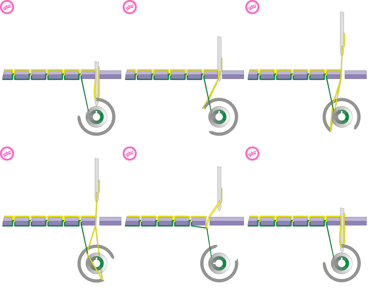
▼The sewing machine
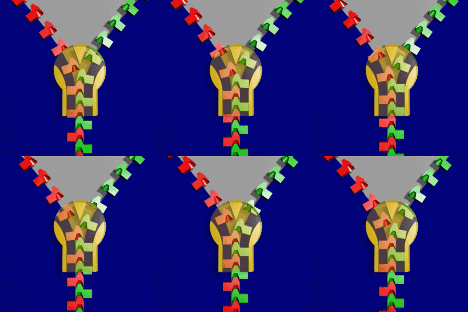
▼zipper
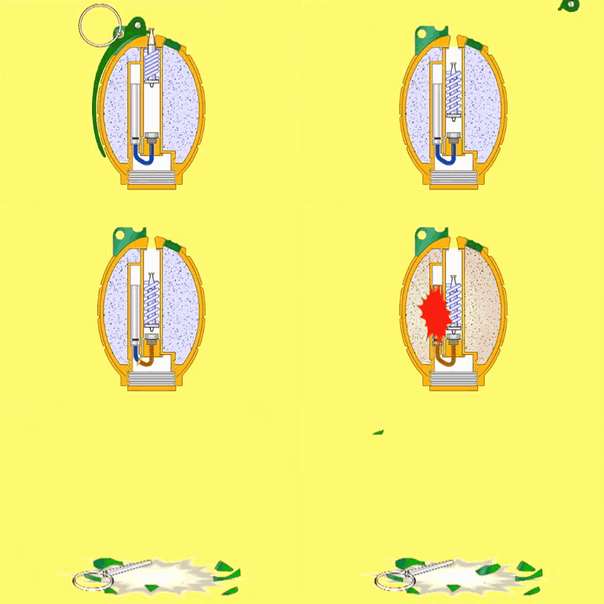
▼A hand grenade
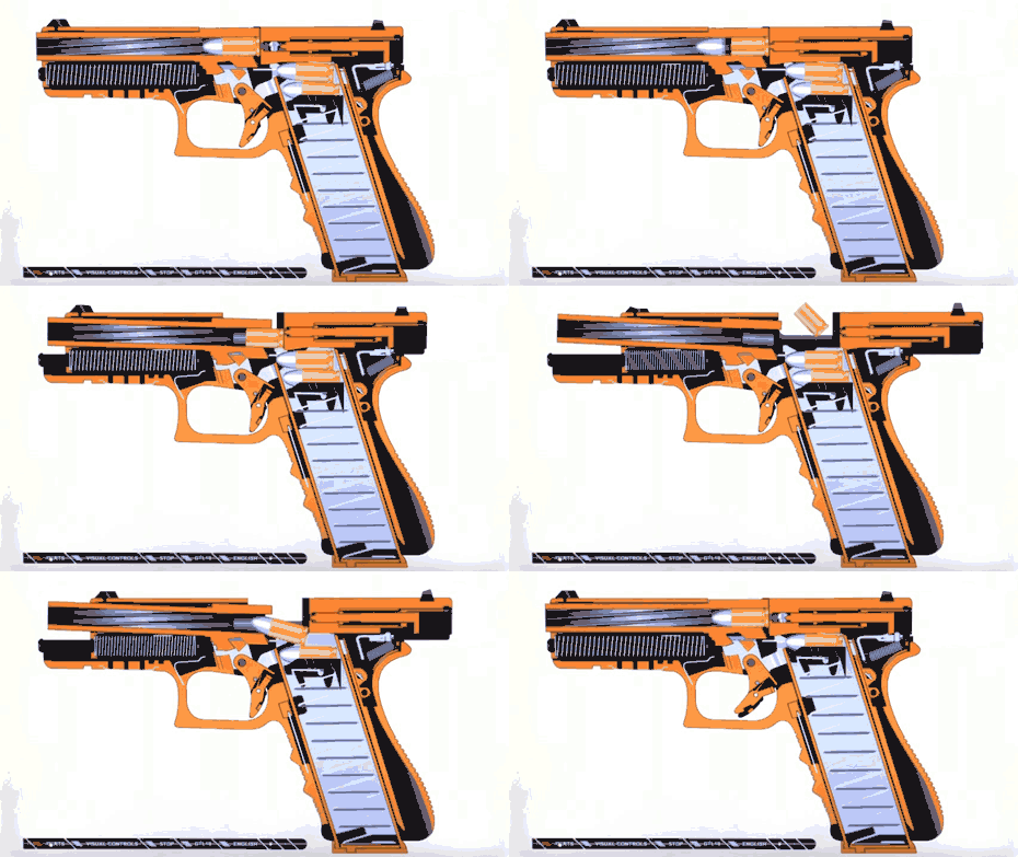
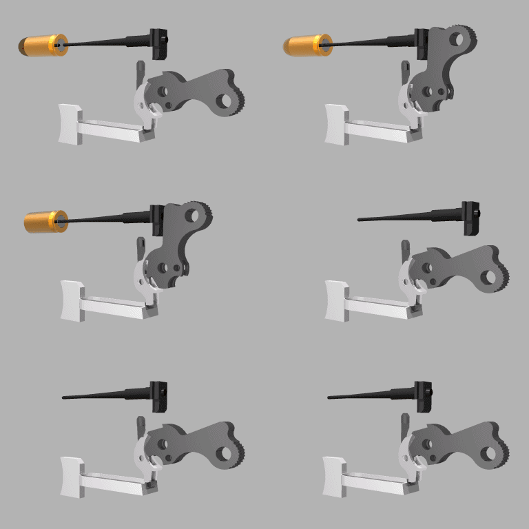
▼The gun
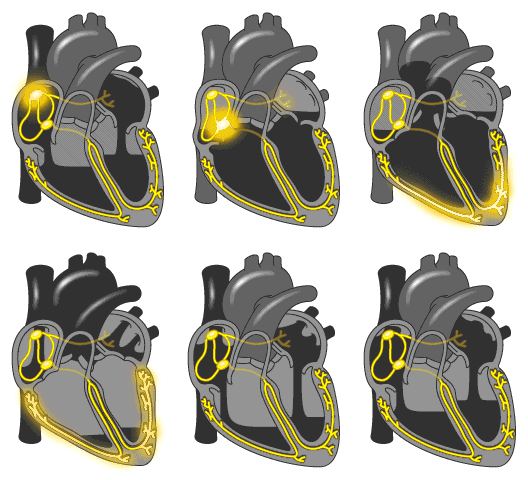
▼The heart
▼Automobile gear

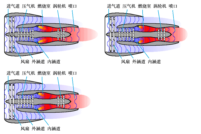
▼Turbofan engine
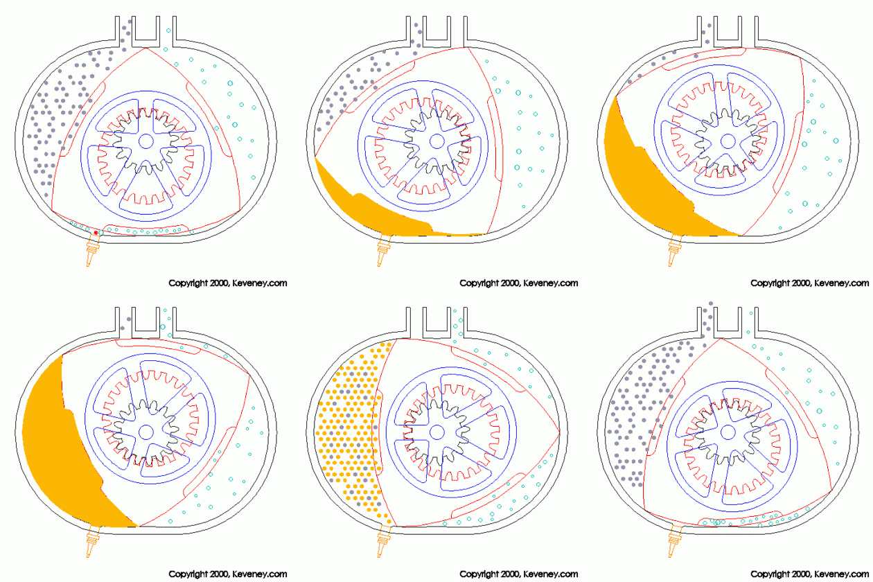
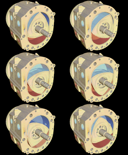
▼Rotor engine
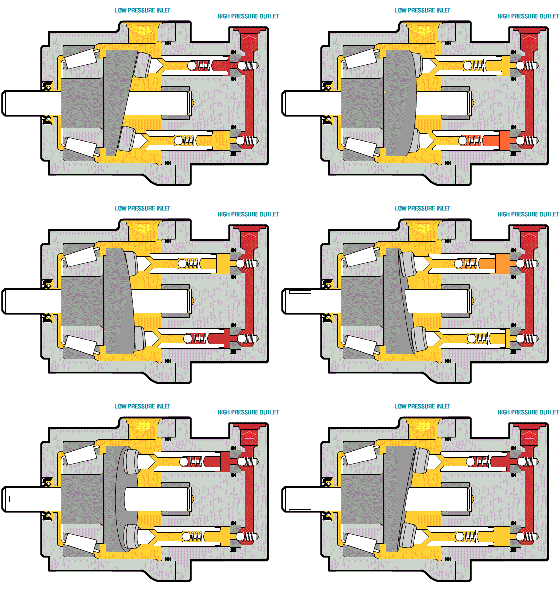
▼Hydraulic plunger pump
▼CAM mechanism
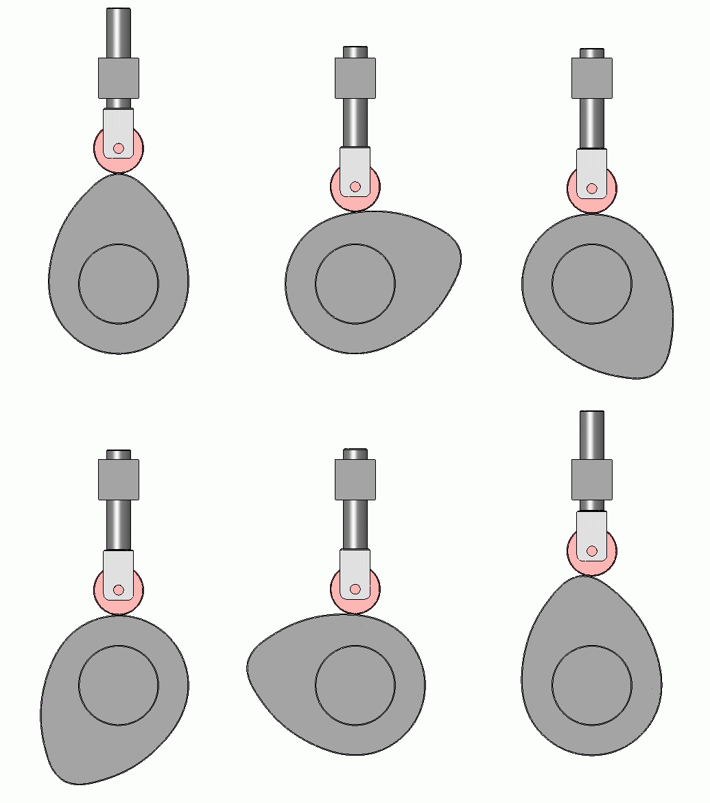
CAM mechanism is a common mechanism in machinery, which is composed of CAM, follower and frame. It can realize automatic mechanical control. A mechanism by which a follower is driven by a rotating or reciprocating motion of a CAM.
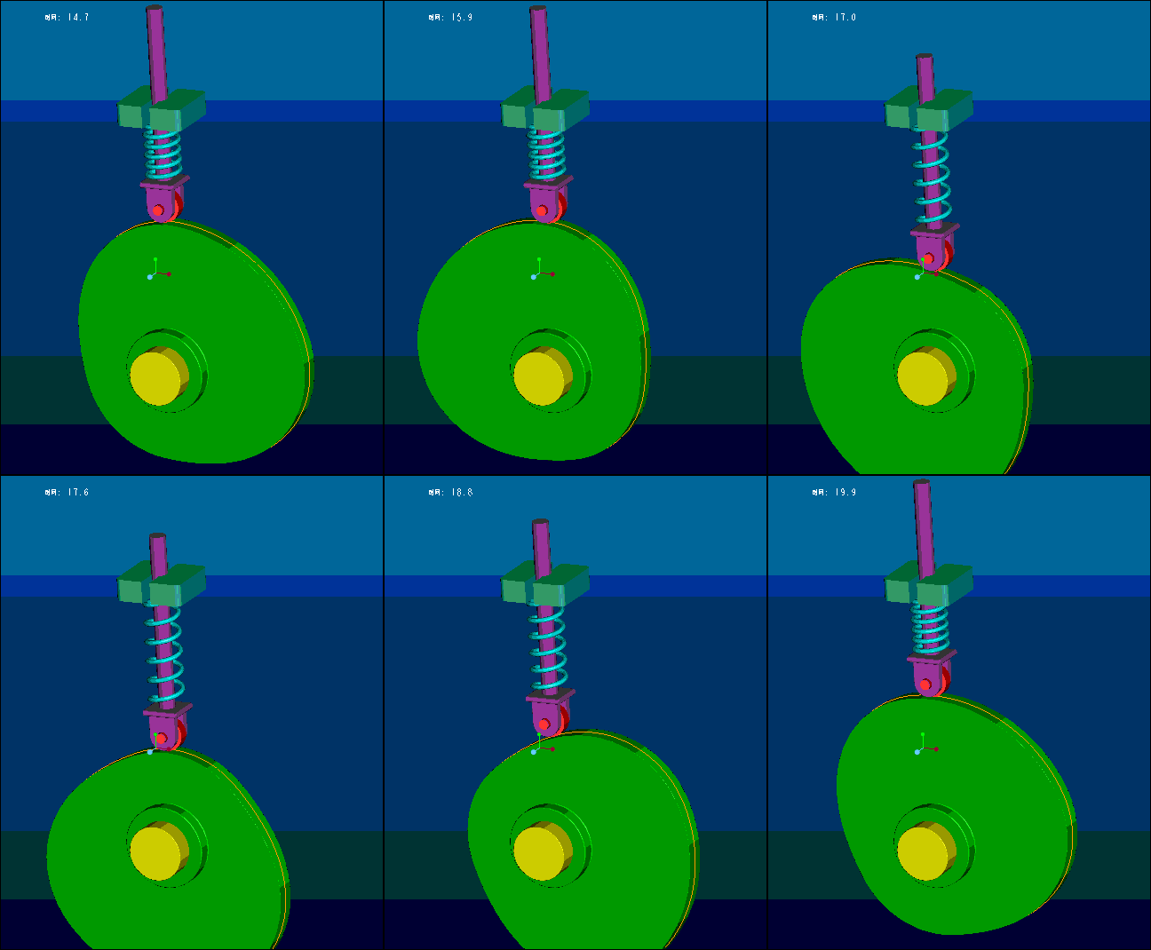
The CAM has a curve profile or groove, disk CAM, cylindrical CAM and moving CAM, etc., of which the cylindrical CAM groove curve is a space curve, so it belongs to the space CAM. The follower and the CAM make point contact or line contact, there are roller follower, flat bottom follower and follower. Follower can maintain contact with any complex CAM profile, can achieve arbitrary movement, but easy to wear, suitable for low speed mechanism with less transmission force.
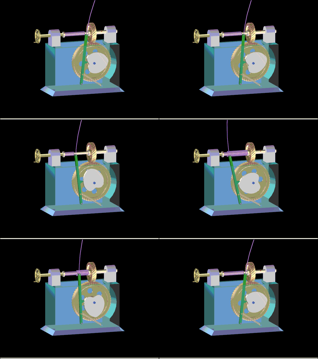
▼Winding mechanism
▼Shooting principle
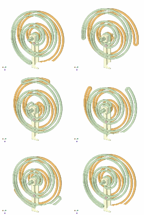
▼Archimedes curve drive
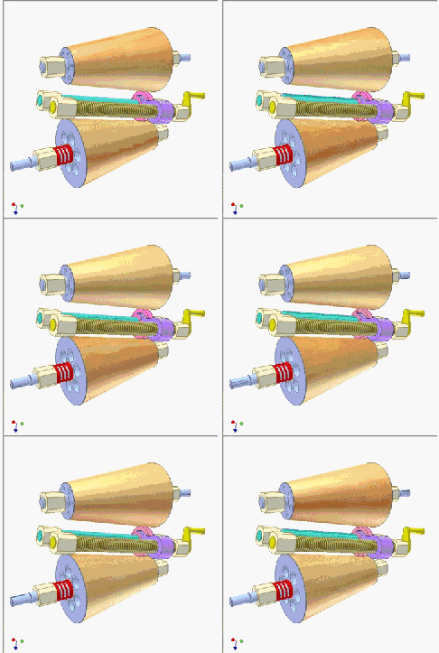
▼Cone friction transmission
▼Crank link mechanism
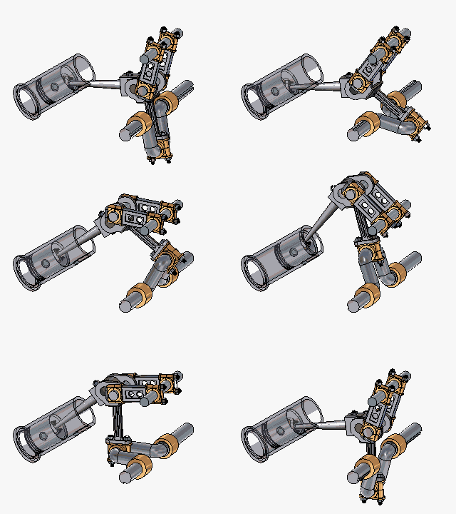
The crank link mechanism is the main motor mechanism of the engine. Its function is to turn the reciprocating motion of the piston into the rotation of the crankshaft, while the force acting on the piston into the crankshaft output torque, in order to drive the rotation of the car wheels. Crank connecting rod mechanism is composed of piston group, connecting rod group, crankshaft, flywheel group and other parts.
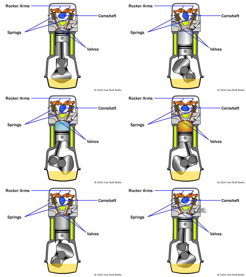
The function of the crank connecting rod mechanism is to provide a combustion site, which converts the expansion pressure of the gas acting on the piston top after fuel combustion into the torque of the crankshaft rotation, and continuously outputs the power. Crank connecting rod mechanism is the main moving part of engine to realize working cycle and complete energy conversion. In the power stroke, it will fuel combustion generated heat piston reciprocating motion, crankshaft rotation motion and into mechanical energy, external output power; In other strokes, the rotary inertia of the crank and flywheel drives the piston up and down through the connecting rod, creating conditions for the next work.
▼ Three stage pump
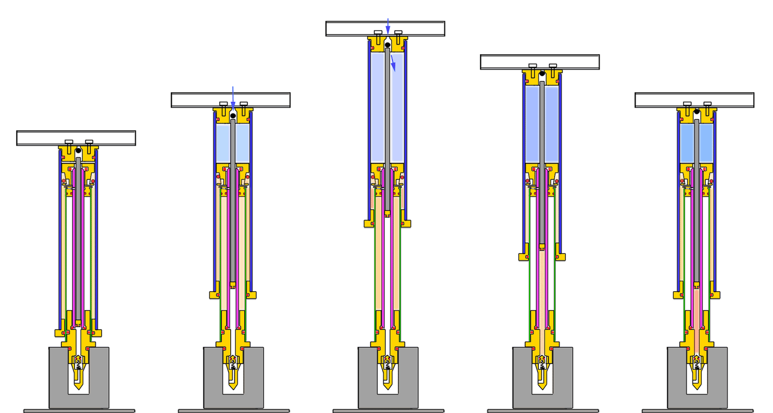
When using a pump, connect its air outlet pipe to the valve of the bicycle tire. The function of the valve is to allow only air to enter the tire from the pump, and do not allow air to reverse into the pump from the tire. There is a gap between the piston of the pump and the wall of the cylinder, and a rubber bowl with a downward recess on the piston. When you pull the piston up, the volume of air under the piston increases, the pressure decreases, and the air above the piston squeezes down from around the rubber bowl. As you press down on the piston, the volume of air below the piston decreases and the pressure increases, so that the rubber bowl is pressed against the cylinder wall to prevent air from leaking over the piston. Continue pressing down on the piston. When the air pressure is enough to push up the valve core of the tire, the compressed air enters the tire. At the same time, the air outside the cylinder passes through a gap at the top of the cylinder to the top of the piston.
↓Lock lever↓
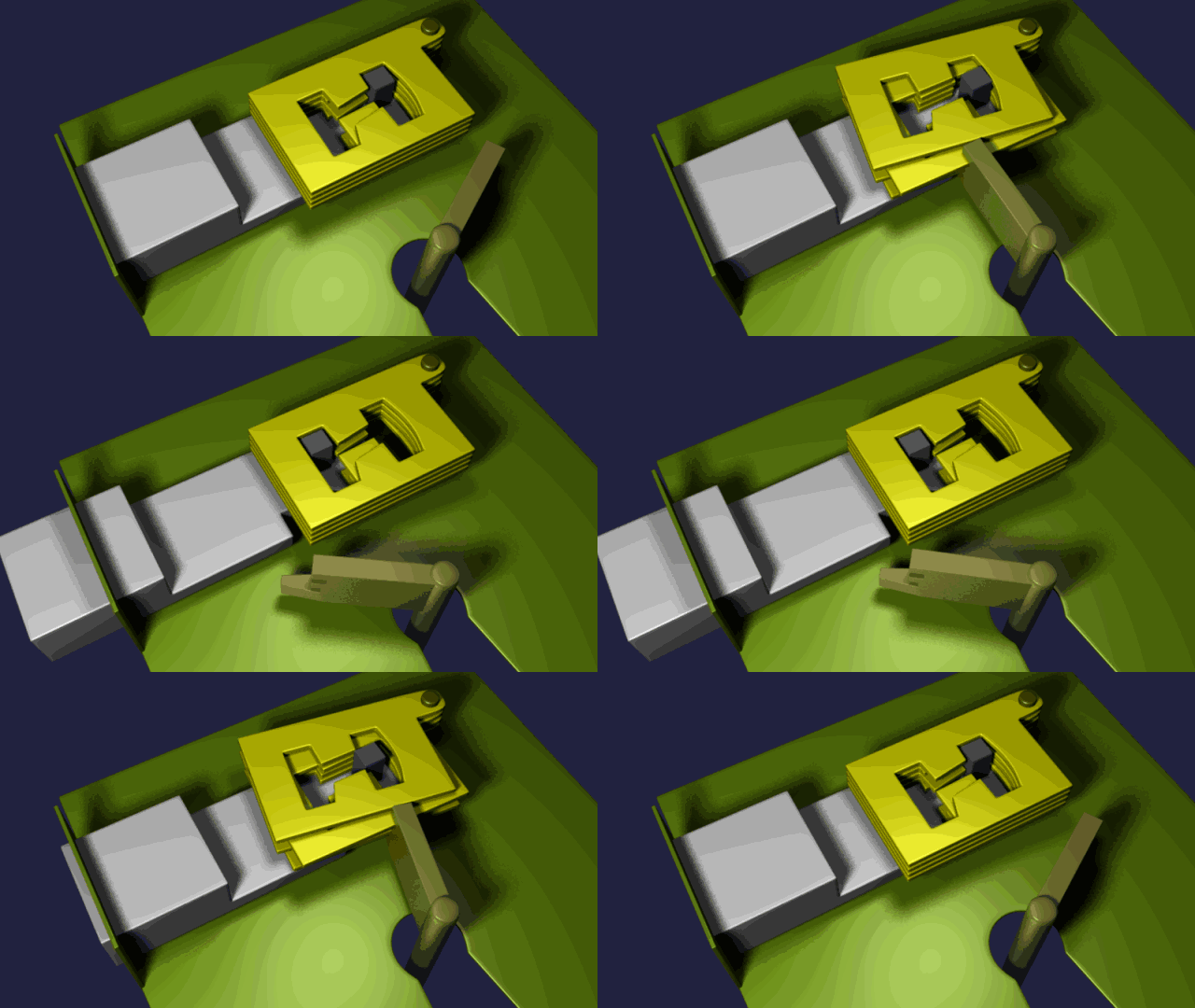
↓Horse other cross core↓
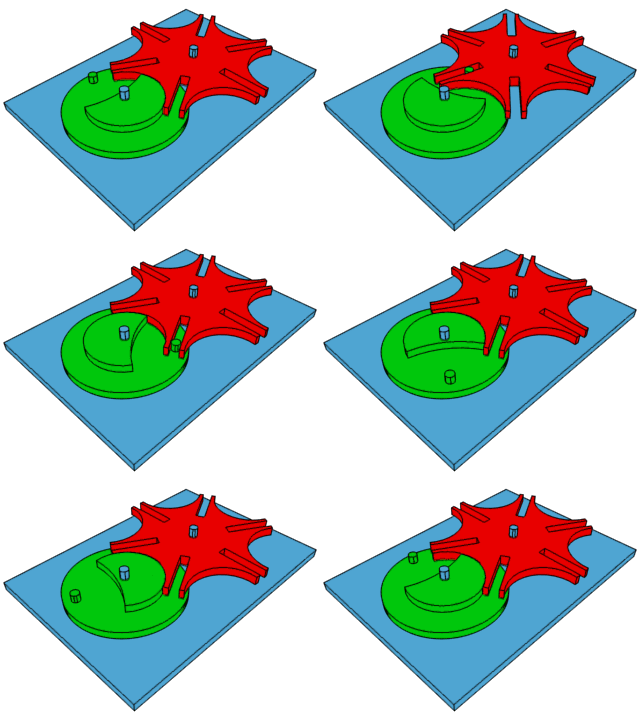
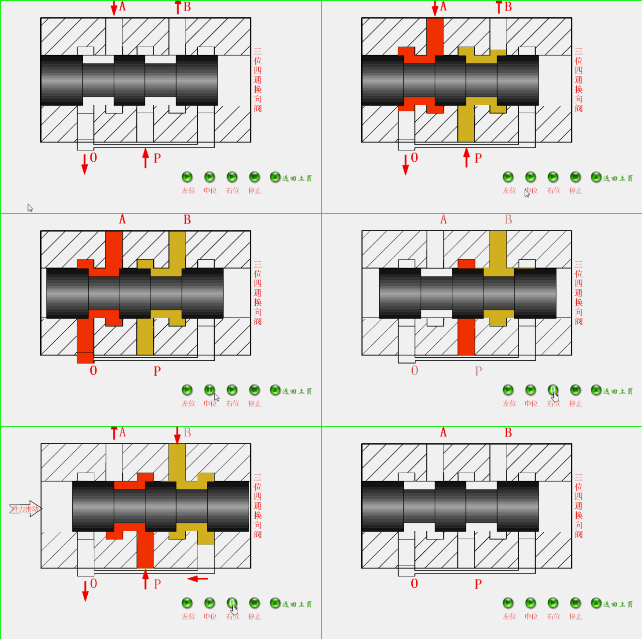
↓Three position four way reversing valve↓
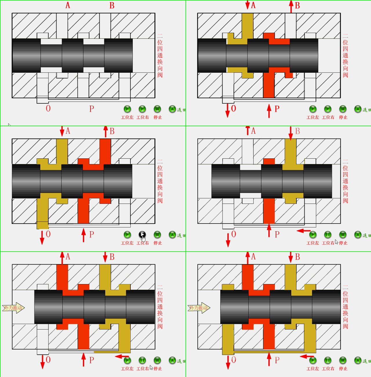
↓Two position four way reversing valve↓
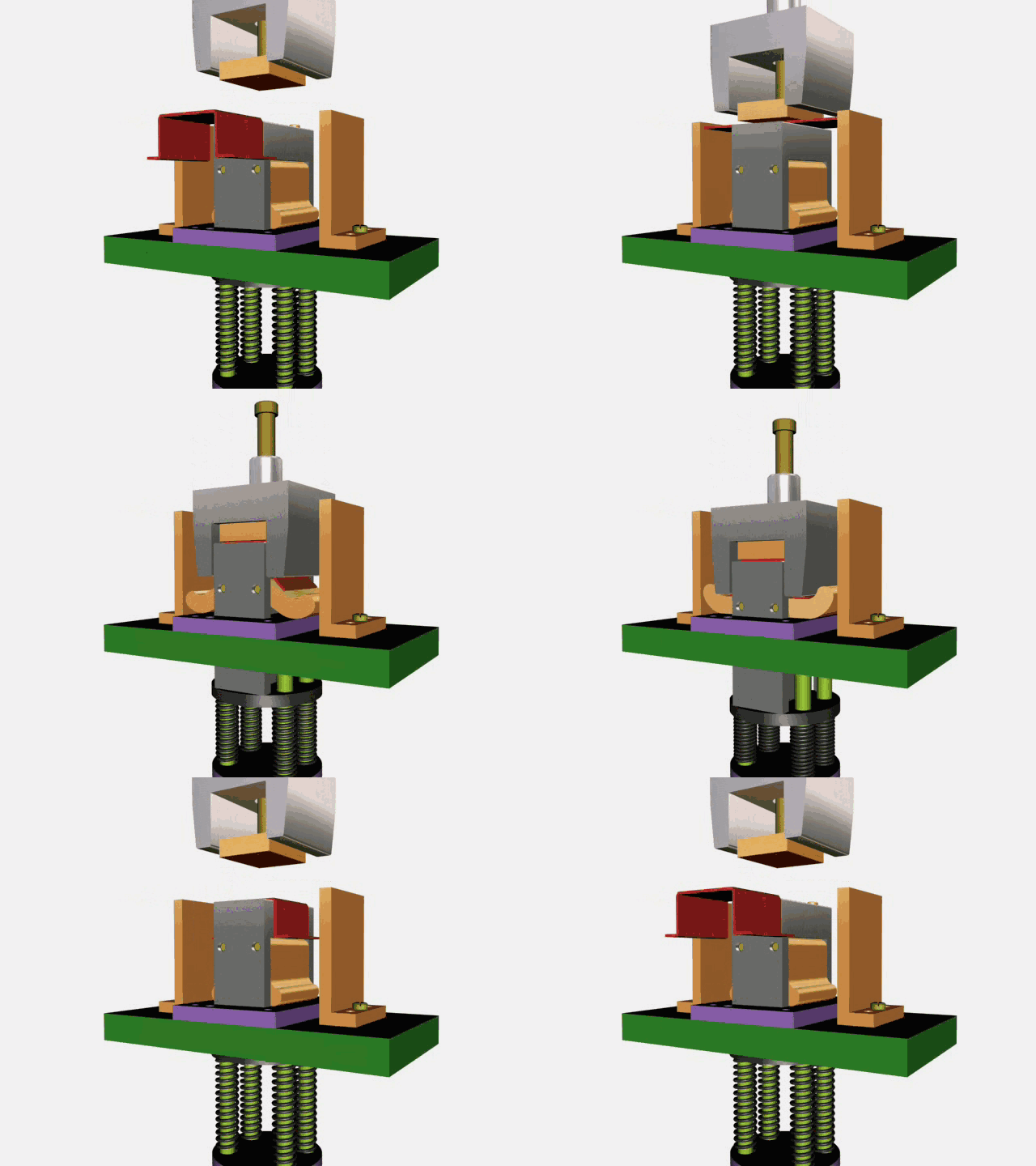
↓The bending of swing block workpiece↓
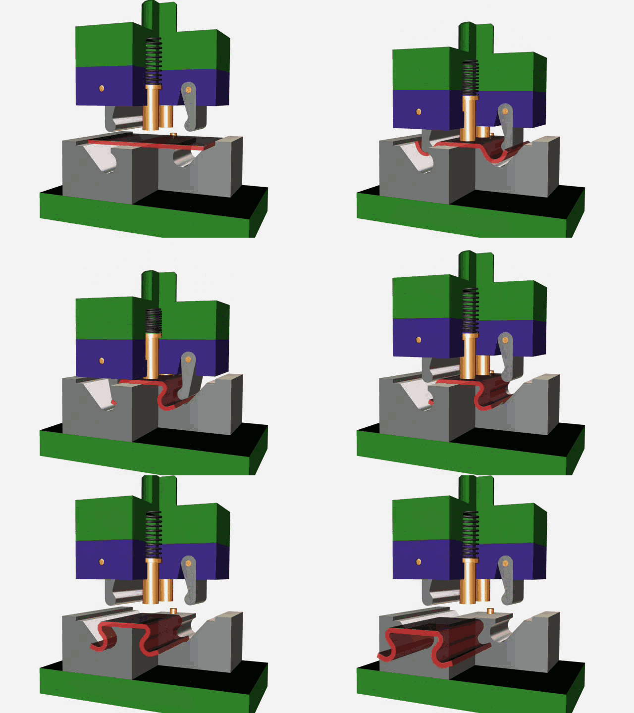
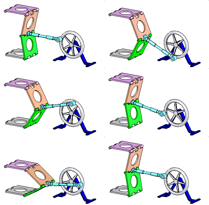
↓Hinge institutions↓
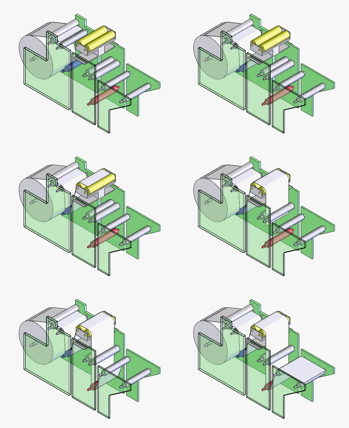
↓Printing agency↓
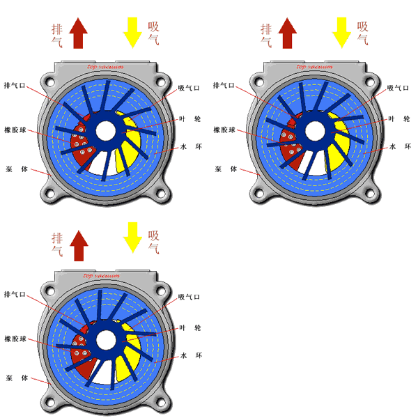
↓Water ring vacuum pump↓
[Working principle] The impeller of the water ring vacuum pump blade is eccentrically arranged in the cylindrical pump shell. A certain amount of water is injected into the pump. When the impeller rotates, the water is thrown to the pump shell to form a water ring, the inner surface of the ring is tangent to the hub of the impeller wheel. Since the pump shell and impeller are not concentric, the intake space between the right half hub and the water ring is gradually expanded, thus forming a vacuum and making the gas enter the intake space of the pump through the intake pipe. The gas then enters the left half, and as the volume between the hubrings is gradually compressed, the pressure increases, so the gas is drained out of the pump through the exhaust space and the exhaust pipe.
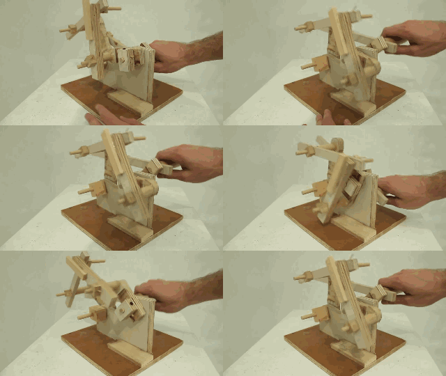
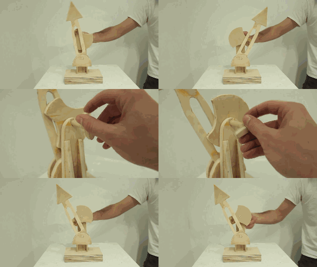
↓Wooden play gifs↓
END


